Engine Position Sensing
As part of my work designing embedded software for propulsion systems, I owned Engine Position Sensing. This consisted of two components; crankshaft position sensing and camshaft position sensing.
Engine Position Sensing is considered a critical component of the architecture because it not only calculates engine speed, but also provides information crucial for accurate timing of both spark and fuel delivery.
Phases of a 4 Stroke Engine
The animation below illustrates the phases of a 4 stroke engine;
- Intake (suck)
- Compression (squeeze)
- Power (bang)
- Exhaust (blow)
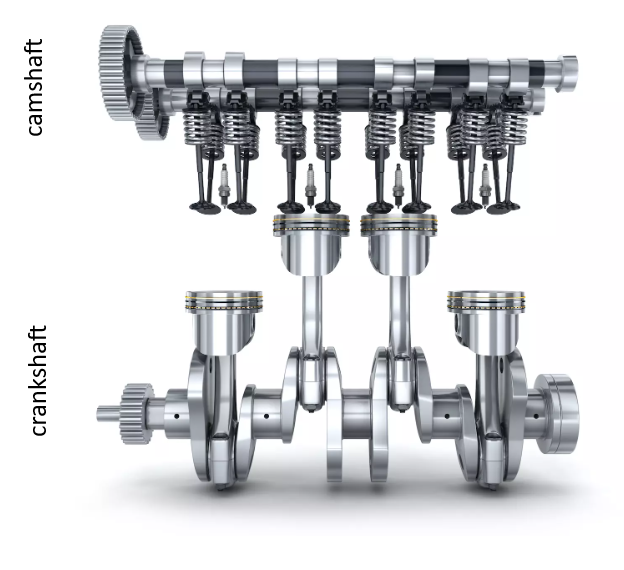
Crankshaft and Camshaft
The crankshaft moves the pistons, and the camshaft moves the intake and exhaust valves.
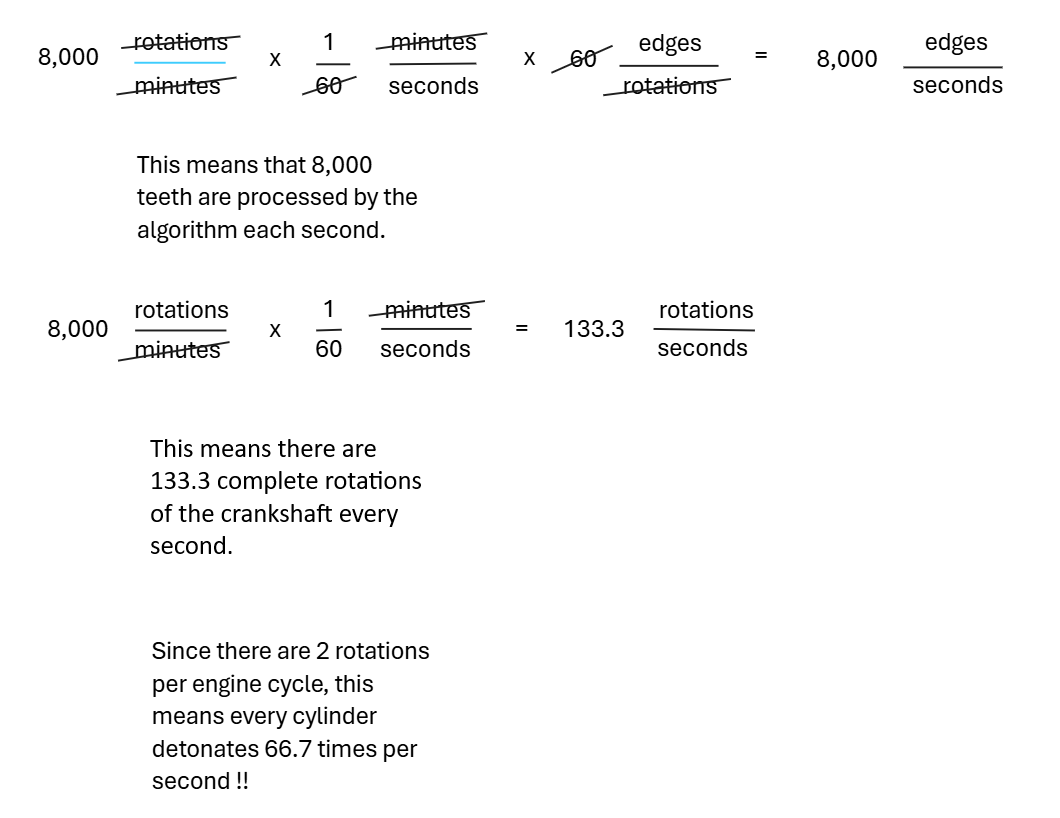
Calculations
To appreciate the complex timing of this machine, consider that it completes this cycle 66 times per second (at 8,000 RPM).
There are 60 teeth on the crankshaft reluctor wheel, evenly spaced at 6 degrees each (i.e. 360/60).
Crankshaft and Camshaft Reluctor Wheels
A crankshaft reluctor wheel (illustrated below) is used to provide the Engine Control Unit (ECU) with precise information about the crankshaft’s position and speed. The reluctor wheel is press-fit onto the rear of the crankshaft and features teeth that pass by a magnetic crankshaft position sensor mounted on the engine block.
As the crankshaft rotates, the passing teeth trigger the sensor, generating signals interpreted by the Engine Position Sensing algorithm.
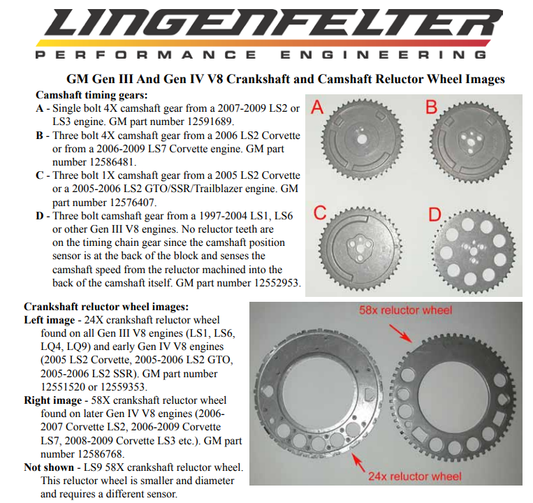
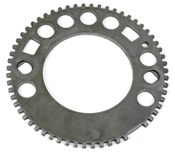
Notice the gap where two teeth are absent. This is knows as the sync gap. It is used as a way to confirm location.